


Mass Air Flow (MAF) sensors play a vital role in modern engines, especially custom intake systems designed for enhanced performance. Strategically placed in the air intake stream, these sensors measure incoming air mass flow rate to ensure optimal combustion and maximize engine power and efficiency. In custom setups with modifications like larger filters or cold air intakes, proper MAF sensor placement is crucial for maintaining accurate air-fuel ratios and controlling engine performance brakes. Optimizing MAF sensor function allows car enthusiasts to fine-tune intake systems, achieving better acceleration, smoother power delivery, improved vehicle dynamics, and enhanced safety features like high-performance brakes.
In the realm of custom intake systems, understanding the strategic placement of a mass air flow (MAF) sensor is paramount for optimal engine performance. This article guides you through the essential aspects of MAF sensor placement in custom intakes, offering insights into their role, accurate reading considerations, and common installation mistakes to avoid. By delving into these factors, you’ll ensure your custom intake system achieves peak efficiency and reliability.
- Understanding Mass Air Flow Sensors: Their Role and Function in Custom Intake Systems
- Optimal Placement Considerations for Accurate Readings in Custom Intakes
- Common Mistakes to Avoid When Installing Mass Air Flow Sensors in Custom Intake Configurations
Understanding Mass Air Flow Sensors: Their Role and Function in Custom Intake Systems

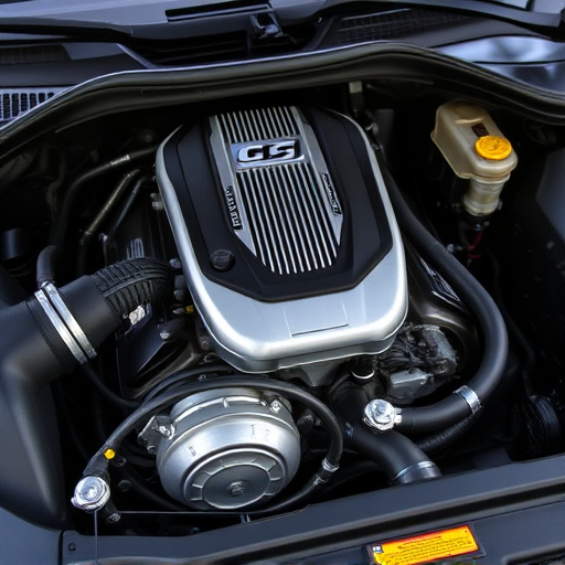
Mass Air Flow (MAF) Sensors play a crucial role in modern engines, particularly in custom intake systems designed to enhance performance. These sensors are strategically placed within the air intake stream to measure the mass flow rate of air entering the engine. By accurately detecting and regulating the amount of air, they ensure optimal combustion, maximizing engine power and efficiency. In custom intake setups, where modifications like larger filters or cold air intakes are introduced, proper MAF sensor placement is essential for maintaining accurate air-fuel ratios.
In these systems, the MAF sensor is typically located near the point where cold, dense outside air mixes with warmer cabin air. This strategic placement allows for precise readings, which are vital for controlling the engine’s performance brakes—specifically, the brake pads and rotors—by regulating fuel injection. By understanding and optimizing MAF sensor function, car enthusiasts can fine-tune their custom intake systems, achieving better acceleration, smoother power delivery, and overall improved vehicle dynamics, without compromising safety features like high-performance brake components.
Optimal Placement Considerations for Accurate Readings in Custom Intakes

Optimal placement of the mass air flow sensor (MAF) is paramount for accurate readings in custom intake systems. Positioning it close to the engine, ideally between the turbocharger or supercharger and the intake manifold, minimizes the impact of backpressure from components like muffler tips. This direct line ensures a true representation of airflow, which is crucial for efficient fuel injection and engine performance.
Furthermore, consider the overall design of the intake system and its various components, such as air filters and charge pipes. The MAF sensor should be secured in an area with minimal potential for obstructions or turbulence from suspension components. A seamless fit, free from abrupt bends or kinks, facilitates smooth airflow, enhancing the accuracy of the readings. This strategic placement allows for precise tuning, maximizing engine output while maintaining optimal fuel-air ratios.
Common Mistakes to Avoid When Installing Mass Air Flow Sensors in Custom Intake Configurations
When installing a Mass Air Flow (MAF) sensor in custom intake systems, several common mistakes can lead to suboptimal performance and potential engine issues. One of the most frequent errors is improper positioning of the sensor. The MAF sensor should be located as close as possible to the engine, ideally in direct air flow from the performance air filter. Misplacing it can result in inaccurate readings and hinder the engine’s ability to maintain optimal fuel-air mixture.
Another mistake to avoid is neglecting proper grounding for the MAF sensor. Ensure that all intake components, including the sensor itself, are properly grounded to prevent electrical interference. Neglecting this detail might lead to erratic sensor signals, affecting the vehicle’s overall performance. Additionally, check for any leaks in the intake system that could contaminate the air flow, and ensure a seamless fit for all brake rotors involved in the air path to maintain consistent and clean air delivery to the engine.
Optimizing mass air flow sensor placement in custom intake systems is key to achieving both accurate performance data and efficient engine operation. By understanding the sensor’s role, considering optimal placement, and avoiding common installation mistakes, you can ensure your custom intake system delivers precise air-fuel ratios, enhancing engine power and fuel efficiency.